SA Actuators
Inertial Actuation for Vibration Generation and Control
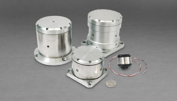
Overview
SA actuators are specified by force capacity and the resonant frequency of the suspended inertial body inside the actuator. The actuators can be driven by a variety of commercially available voltage or current amplifiers. Moog CSA Engineering offers standard off the shelf SA actuators in two sizes which are detailed in this datasheet, the SA1-V40 and SA10-V20.

Custom SA actuator design is offered and may be scoped in the form of small changes in the mechanical interface, electrical interface, impedance, or resonant frequency of the unit. Comprehensive ground up design is also offered for the most challenging of applications with full consideration of environmental and performance specifications. Vacuum compatible versions are available.
A typical representative frequency response curve (FRF) for SA actuators is shown above. SA actuators will exhibit a primary resonance at a designed frequency. The dynamic mechanical amplification characteristic near resonance can be utilized to output higher force levels for a given input power. This can be useful where power consumption is a concern. At frequencies above the primary resonance, the actuators will output forces of magnitude that is relatively linear with respect to input current. The second peak shown in the FRF at 1kHz is a resonance associated with characteristics of the host structure used during measurement.
Hardware Specifications*
| SA1-V40 | SA10-V20 | |
| Moving Effective Weight | 0.07 Lbs (.032 kg) | 3.3 Lbs (1.50 kg) |
| Total Device Weight | 0.23 Lbs (.104 kg) | 5.9 Lbs (2.68 kg) |
| Standard Mounting Interface (See mechanical dimensions for details) | Stud | Flange |
| Standard Electrical Interface (See mechanical dimensions for details) | 9”min 24 AWG Stripped Leads | 12” min 20 AWG Stripped Leads |
| Construction | Various metals, treated to enhance durability and corrosion resistance. BOM available upon request. | |
Performance Specifications*
| SA1-V40 | SA10-V20 | |
| Available Stroke | ±.085 in (2.2 mm) | 0.16 (4.0) |
| Force Constant | 0.85 Lbf/amp (3.8 N/amp) | 3.4 Lbf/amp (15.1 N/amp) |
| Standard Resonant Frequency | 40 Hz | 20 Hz |
| Q Factor | 2.6 | 7 |
| Electrical Resistance | 4.2 Ohms | 4.0 Ohms |
| Electrical Inductance | .5 mH | 1.4 mH |
Thermal Performance*
| Thermal performance varies widely depending on ambient environment and thermal characteristics of the host structure. Provided below are basic guidelines and approximations for user reference in a controlled laboratory environment. The actuator housing temperature should be monitored and maintained well under the max operating temperature during usage to avoid damage to the actuator. Wider temperature ranges available upon request. | ||
| Maximum Operating Temperature | 80°C (176°F) | 80°C (176°F) |
| Max RMS Current (power) [force] (applied for 60seconds) | 2.5 amps (26 watts) [2.1lbf] | 6.0 amps (144 watts) [20.4 lbf] |
| Max RMS Current (power) [force] (applied continuously) | 1.2 amps (6 watts) [1 lbf] | 2.9 amps (34 watts) [10 lbf] |
*All tables represent typically measured values. Actual performance and specifications may vary